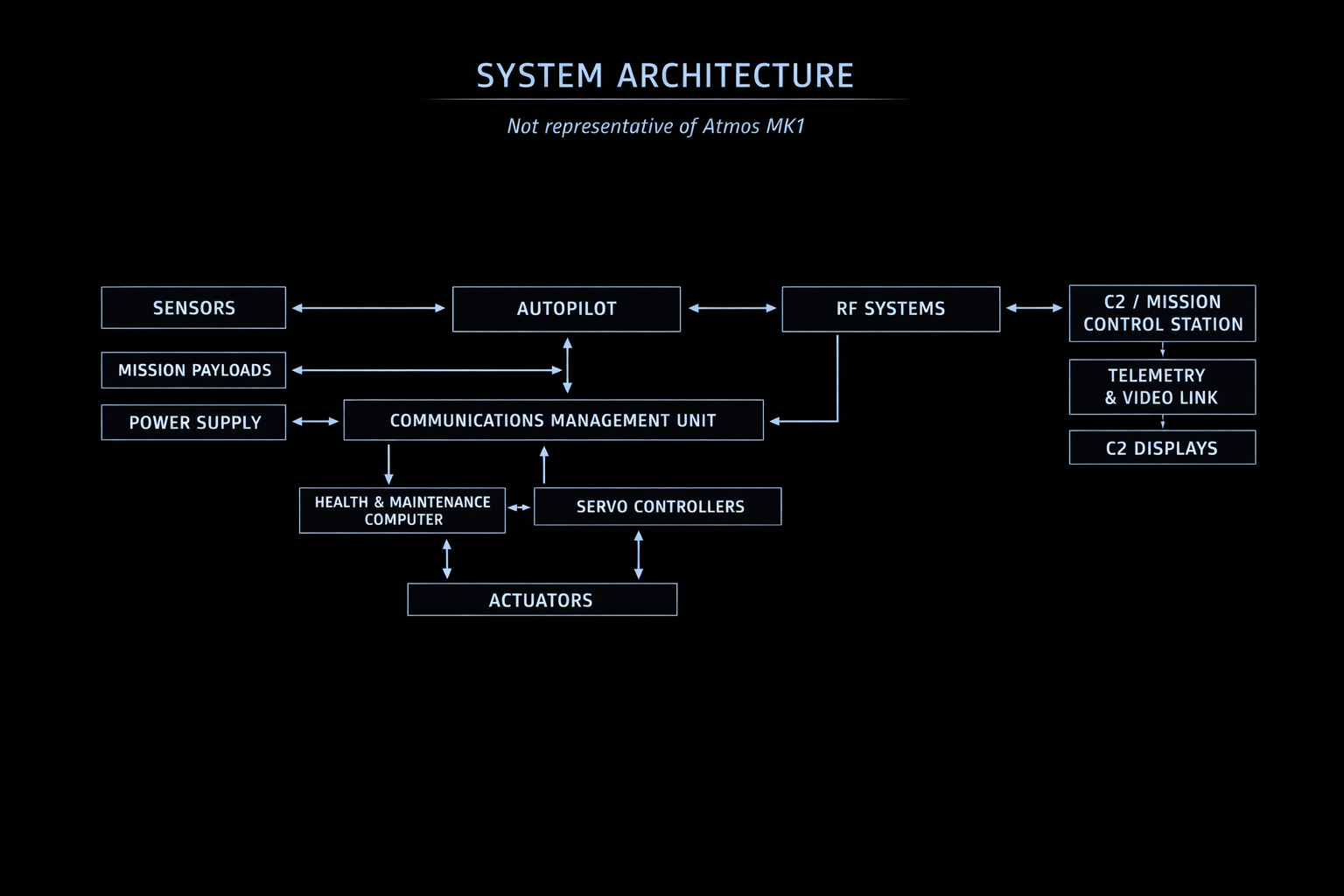
The Atmos Mk1 project began with me designing the initial electrical system architecture and later evolved into more of a lead systems architect role as the project and team expanded. Using a top-down design approach inspired by proven Radio Control (RC) aircraft architectures, I defined the first high-level avionics and power system layout capable of stratospheric operation.
As the system matured through multiple design iterations and flight testing, the platform successfully reached altitudes above 56,000 ft, validating the early architectural decisions — many of which remain in the flying system today.
What I Worked On
I focused on the high level system architecture as well as the following domains in detail:
- Power systems (e.g. Battery, Solar, Power conversion, Power distribution, etc.)
- Embedded systems (excluding autopilot)
- Lighting systems
- Data collection and telemetry
- Ground station architecture and network infrastructure (including uplink/downlink)
- High-level spatial allocation of avionics, power, and payload systems within the airframe
I generated several requirements documents for systems and subsystems, defined test standards. Design decisions ranged from simple choices such as cable insulation materials, bus voltages, and communication bus types to more complex decisions involving power distribution unit (PDU) architecture, battery design and RF system choices. I designed the first eight architecture versions, iterating alongside flight testing, before transitioning the design ownership to the team and mentoring them through the next 10+ major versions.
The architecture itself evolved from an initial high-level block diagram into a comprehensive reference document — covering wire gauges, harness lengths, wire colours, connector pinouts, and images of each device alongside relevant model numbers, all laid out to reflect the physical layout of the actual aircraft. The ground station architecture was developed to a similar level of detail, and dedicated architecture diagrams were produced for every payload integrated into the aircraft.
I also worked on various other smaller airframes where in some cases I led the system architecture, PCB design and integration. I was able to apply many of the same methodologies and learnings from the Mk1 platform, but on a much smaller and more compact scale. These aircraft were restricted to low altitude flights (below 10,000ft) due to airframe limitation which in turn simplified design constraints.
Challenges
Many of the challenges revolved around operating within an environment where there was little information on and very few people had the experience of operating within. Other challenges were created directly from requiring a low SWaP (Size, Weight, and Power) vehicle in almost every aspect to achieve stratospheric flight. Operating in the stratosphere meant the entire system could be subject to challenging conditions such as temperatures below -55°C, pressures below 60mbar (very low but not yet considered a vacuum), and radiation to name a few. Furthermore, flying the Atmos Mk1 UAV from ground level to the stratosphere also meant the entire system must operate reliably in two very different environments and any weather system it may pass through along the way. This was a challenge for various aspects of the initial avionics design such as thermal management challenges caused by low atmospheric density, along with outgassing and high-voltage arcing considerations. These challenges were overcome through careful selection and research into subsystems and/or components prior to purchasing or designing. In many cases I designed and performed environmental and electrical validation tests on components and subsystems to not only ensure they could operate under stratospheric conditions but also have high confidence in their reliability. In other cases it was obvious, whether through testing or looking at the datasheets, that some components or subsystems required modifications such as thermal management circuits, custom heat sinking or conformal coating.
General Approach
Factoring in the company’s expected 2 year project timeline, limited in-house skill coverage and limited budget, I needed to determine what systems could (or should) be purchased off-the-shelf, and what systems could (or should) be manufactured in-house or even outsourced. My decisions on this matter were heavily influenced by what could be done to get the first prototype flying as soon as possible and what subsystems might require the most R&D to get the first prototype in the stratosphere as soon as possible. I prioritized getting a flyable prototype into the air as early as possible rather than pursuing a perfect theoretical design with many undiscovered unknowns. This approach allowed the company to quickly iterate on procedures, designs and systems to create a significantly more reliable UAV. Redundancy was another area that I had to compromise on initially in almost every area due to the low SWaP constraints, therefore creating a need for systems to be thoroughly tested and the capability of doing so to be within reach.
For subsystems where the solution was unique to our application, needed to remain flexible, or where no suitable product existed, I prioritised in-house design. This gave us the greatest control over the final solution. On rare occasions where in-house capability was lacking, I worked with external contractors instead.
Where existing products suited our application, or the effort to reinvent the wheel wasn’t worth it, I prioritised COTS. In some cases I flagged specific COTS choices as stepping stones — good enough to get flying, but earmarked for replacement once the system was proven. I was careful to ensure all COTS selections had a clear integration path on paper and, where possible, a fallback option.
Key Takeaways
I was genuinely surprised by how much of the initial architecture is still flying today. A lot of the early decisions — particularly around power distribution and how systems communicate — were never revisited, partly because they worked and partly because there was always more important work to do. That’s both a compliment to the early design and a caution: the communication architecture that made sense in the early stages is now deeply embedded, and changing it would mean a full redesign rather than an incremental improvement.
The power distribution design in particular held up well. The way I structured it gave the team a lot of flexibility in where loads could be physically placed and powered as the design evolved — something I hadn’t fully anticipated would matter as much as it did.
On the integration side, I learned a lot about the hidden consequences of placement decisions. Power conversion devices with significant heat rejection need to go somewhere the heat can actually go — which in a near-vacuum is a harder problem than it sounds. In a weight-optimised airframe, every structural member is sized for its specific load case — which means vibration profiles across the structure can vary in ways that aren’t always intuitive. Placing critical avionics without accounting for this can lead to reliability issues that are hard to diagnose later. Payloads need to be accessible and easy to swap, especially when future payload requirements are unknown. And the whole system needs to stay serviceable — you can pack a lot into a tight airframe, but if you can’t debug it or pull it apart in the field, you’ve made a problem for yourself.