A HAPS typically flies in the stratosphere above the weather systems and thus will always see the sun during the day. This means a HAPS can fly solely off solar power in daytime due to their wings typically containing large solar arrays providing excess energy. However, when flying during the night, one of the biggest challenges for a HAPS is having sufficient energy storage such that it remains in the stratosphere overnight for days on end.
There are various different ways to store energy for HAPS, but only one practical solution exists for a long-endurance HAPS, specifically Kea Atmos. During my research it became immediately clear that Lithium batteries were the only real solution to this problem despite knowing the technology had some rather large limitations at the time. Lithium batteries can provide high-energy density storage with the ability to replenish this energy (i.e. through the day using solar) where in simple terms they will go through one charge/discharge cycle every day. The issue with high-energy density batteries is that there is a trade-off between high capacity and cycle life, meaning these batteries typically do not last long (in the order of days). As they wear out, their total capacity reduces, meaning there is less energy every single night. This directly adds to the challenges of ensuring sufficient energy storage and also the long-endurance aspect of a HAPS.
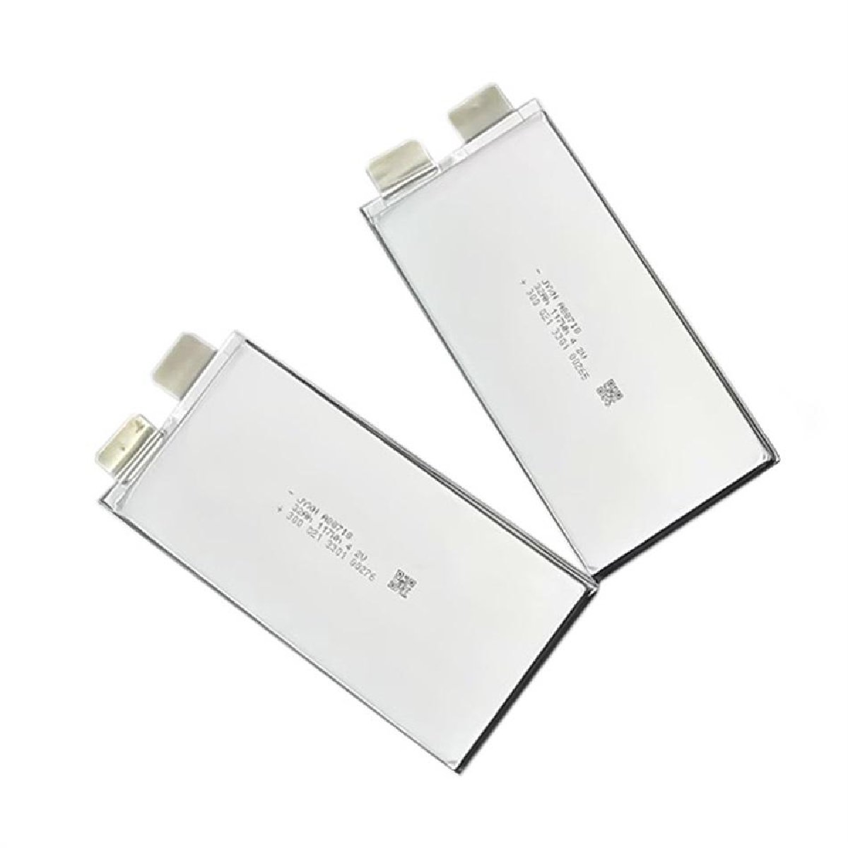
Image: Example of a Lithium pouch cell
The biggest energy users on a HAPS are the propulsion system, thermal management systems, payloads and RF systems. Reducing energy usage of these systems can significantly reduce the challenges seen in designing the energy storage system.
Designing the battery pack for the Atmos Mk1 was my responsibility — from initial research and cell selection through to electrical design, pack construction and integration. It was my aim to ensure that the pack had the highest energy density possible without sacrificing endurance. The capacity I could achieve set a hard ceiling on the energy budget for every other system on the aircraft overnight.
What I Worked On
- Researched, selected and procured lithium cells, including supplier management
- Designed the current collector interconnect method for the pack
- Defined the geometric layout of the pack and the placement of cells
- Designed, tested and integrated a custom Battery Management System (BMS) and supporting circuitry
- Manufactured the first prototype packs
- Developed custom procedures for manufacturing, health & safety, charge/discharge, storage, testing and flight operations
- Led development of data driven models of the pack characteristics
- Capacity
- Charge/Discharge efficiencies
- DCIR and ACIR
- Effects of compression and temperature changes
Challenges
Bus Voltage
The bus voltage decision ended up being more restricted than I expected going in. The solar system (notably the array geometry, cell configuration and MPPT count) was already locked before I started on the battery, which cut down the options for how the pack could be arranged. The solar side ended up driving more of the battery architecture than I’d have liked. My preference was to run a higher bus voltage to keep wire mass down without overcomplicating the design during what was a fast R&D phase, but what the solar system could support put a ceiling on that and so did the availability of common ICs at that time. Fully working through energy system constraints early, especially before the airframe design is set, was an essential lesson for myself and the team. Changing solar cell geometry after the airframe design has been locked in is a very different problem to solving it at the concept stage.
Cell Interconnects and Manufacturability
Lithium cells have aluminium cathode tabs and nickel anode tabs, and getting a reliable joint between them in a hand-built pack is harder than it sounds. You can’t solder aluminium with standard techniques, and spot welding it turned out to be far less reliable than with nickel — aluminium’s high thermal conductivity and its tendency to re-oxidise almost instantly makes getting a consistent weld very difficult, and the results reflected that. I spent a fair amount of time testing different approaches, including developing a method for soldering aluminium tabs directly — that didn’t end up as the final solution, but the time wasn’t wasted either. Whatever the method, it needed to be electrically reliable, hold up mechanically, and be something I could reproduce by hand consistently. Getting to that point took real iteration on materials, tooling and process.
Thermal
Testing thermal performance was trickier than I anticipated. Running single cells through a thermal chamber was straightforward but the results were essentially meaningless — the heat rejection from a single cell was so low it barely registered and I could not produce repeatable or accurate results. Testing a full pack gave much more useful data, especially considering any thermal insulation the pack may have had, but validating at stratospheric conditions is a different problem. That requires a TVAC chamber, which isn’t easy to get time in. Most of our validation ended up being thermal and vacuum tested separately, supported by simulation. Honestly, flight testing was where the most useful data came from. On top of that, deciding where and how to pull heat out of the pack was its own challenge — there are a few ways to approach it, but the lightweight constraint ruled out most of the obvious options and required careful thought about what was actually feasible. Adding survival heaters in the mix also meant we had to find ways to mitigate unintended heat losses.
General Approach
Given the novel nature of the application, a lot of groundwork had to be laid early. I developed a suite of custom procedures covering health and safety, manufacturing, charge and discharge protocols, storage, testing, integration, logistics and flight operations. Without these, the iterative nature of the work would have been much harder to manage safely and consistently.
BMS and Pack Design
The pack design had to balance a lot of competing constraints simultaneously. Weight was the primary driver — every gram mattered at stratospheric altitude — which put pressure on packing factor, cell arrangement and everything else. The geometric layout had to account for thermal management, compression (cells expand and contract across charge cycles), BMS and interconnect routing, integration with the surrounding structure, and the practical reality of being able to build and service it by hand.
The BMS and cell interconnect design ended up being tightly coupled as a result of the geometric layout — a consequence of optimising hard for space and weight. This worked well for design simplicity and robustness, but it also meant the design wasn’t easily scalable to a next-generation aircraft. The Mk2, which is significantly larger, would need a different approach.
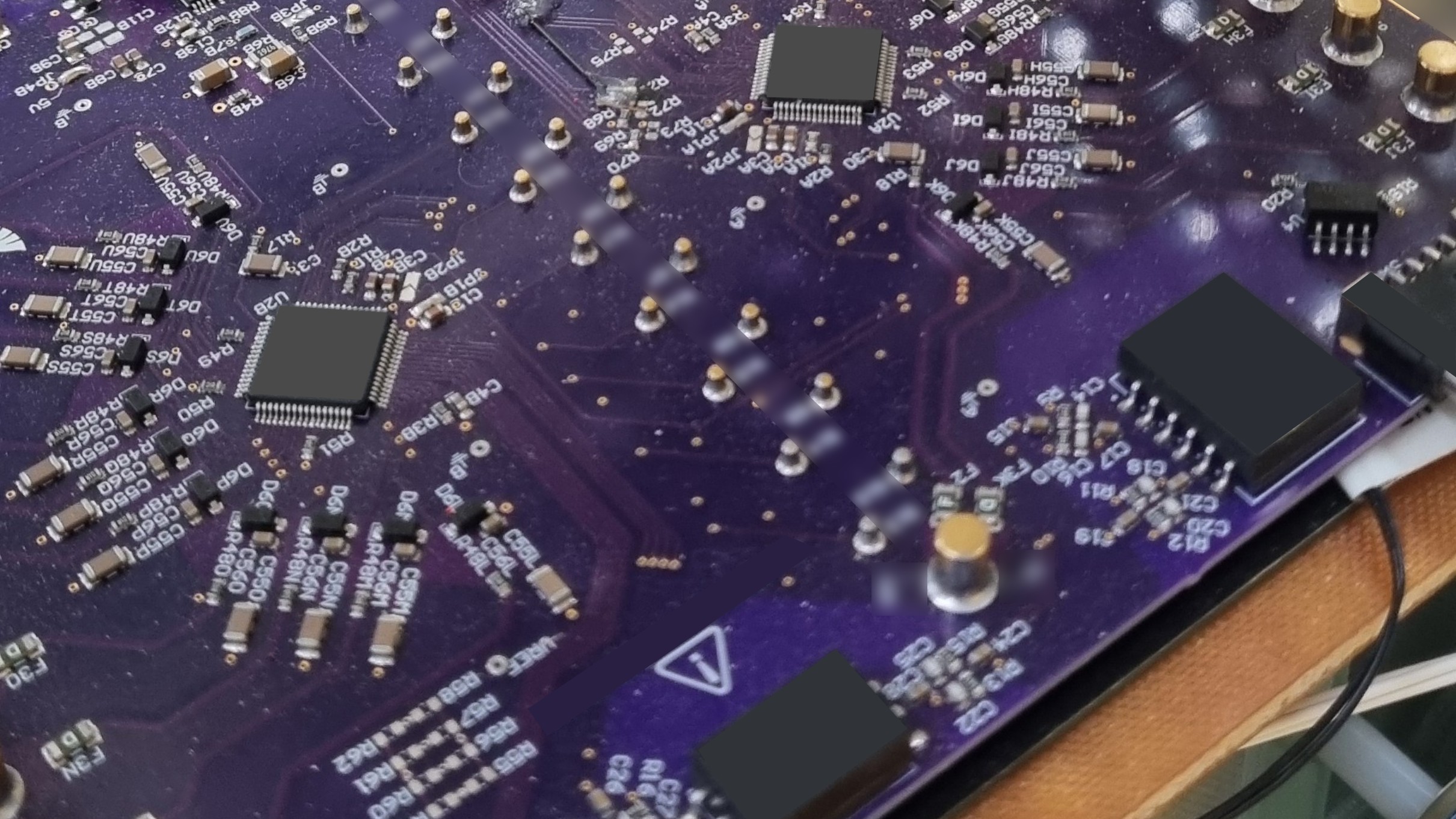
The BMS was designed entirely from scratch. Before committing to the full PCB design, I built smaller prototype boards to test specific circuits and layout techniques in isolation. The final architecture was designed to be scalable, with robust communication links and enough flexibility to accommodate changes across revisions and future pack generations. It included integrated heater control, redundant methods for tracking SOC, and was designed to be modular — so any pack in the fleet could have its BMS upgraded or replaced independently of the cells. Before testing the BMS on a real battery pack, I built a custom development board — essentially a sandpit that could simulate a battery and mock sensor data — to prove out the circuitry and validate the BMS performance.
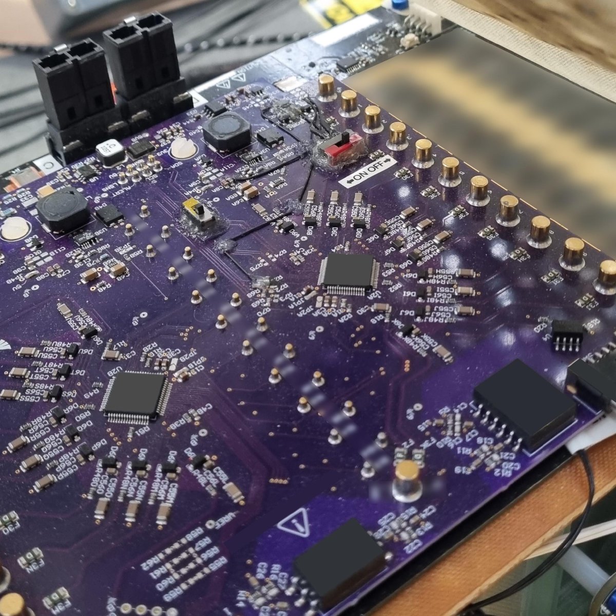
Image: Closeup of BMS on early prototype battery pack
Pack Manufacturing
I developed custom tooling and assembly processes for building the packs by hand. Risk management was a real part of this — working with high-energy-density lithium cells in a small team requires careful process control, and the procedures I put in place were as much about safety as consistency. Early prototype builds in particular required a methodical approach given the unknowns involved.
The pack also had a fair amount of harnessing integrated directly into the pack, e.g. temperature sensors and heaters for the thermal control system. Several other harnesses were created for the BMS and other circuitry interfacing directly with the pack where reliability needed to be ensured. Getting this right was as much a part of the manufacturing process as the pack assembly itself, since unreliable connections here would have been difficult to diagnose later. A mix of direct soldering to PCB and high-reliability wire-to-board connectors were used.
Testing and Validation
I built a custom testing station that also served as a dedicated charge/discharge rig. This let me generate full pack curves and validate the BMS under controlled conditions across a range of states. Before any flight testing, I ran extensive ground tests using solar array simulators and real loads including the propulsion system — the goal was to understand how the whole system behaved together across its full operating range, and to build confidence before the battery went in the air. Once flight testing began, I took an incremental approach — pushing the battery progressively harder across flights, extending to higher altitudes and longer durations as confidence in the system grew. The combination of ground simulation and incremental flight testing gave a much more complete picture of real-world performance than either approach alone would have.
Key Takeaways
Working on a genuinely novel application meant there was very little to reference — no established playbook for stratospheric lithium battery packs at this scale. A lot of the work was building knowledge from scratch, which made the early testing and procedure development as valuable as the design itself.
The bus voltage challenge was a good early lesson in how tightly coupled energy systems are. A decision made upstream on the solar side had real consequences for what I could do with the battery, and by the time I encountered that constraint, there wasn’t much room to change it. It reinforced how important it is to work through these interactions at the concept stage, before any part of the system gets locked in.
Without any prior reference data, validating models was genuinely difficult early on. Lab testing in isolation told part of the story but not all of it — flight was where the real understanding came from. The upside is that all of that data now exists. Going into a next-generation pack design, there’s a real starting point to build from and a clear picture of what to avoid.
Testing incrementally — gradually pushing the battery harder across flights rather than heading straight to the limits — made sense given the circumstances. The battery wasn’t the only system being validated in flight; RF and autopilot were also being tested simultaneously, both carrying their own risk. Going straight to the limits with multiple untested systems in the air at once, with only one flying prototype and a tight timeline, wasn’t a sensible call. In hindsight, the ground testing gave enough confidence that we could have pushed harder sooner — but the incremental approach also caught that the thermal solution wasn’t performing quite as expected, something that might have been missed in a more aggressive programme. The data gathered across those flights was worth it.
Time spent on approaches that didn’t make the final design — the aluminium soldering work, the spot welding attempts — wasn’t wasted. It built experience the company could draw on across other projects, and it gave a well-reasoned justification for the engineering path we did take. Knowing from first-hand testing why something doesn’t work is a much stronger foundation for a decision than assuming it won’t.